Breaking down the visuals of SkyLei
Up until last December, I worked on a game called SkyLei. The game was written based on a custom game engine in C++ and OpenGL, where I developed a most of the rendering pipeline. I finally found the time to break down the different graphics techniques and architecture decisions for the rendering part of the SkyLei, so that’s what to expect from this post. Just in case anyone was interested in learning more about it.
This article is intended for those with intermediate experience with graphics programming and some understanding of the OpenGL graphics API is needed. With that said, I will try to keep the explanation of each graphics technique used at a relatively high level, rather than delving deep into the maths and dry knowledge, so everyone can hopefully see the big picture and the more enthusiastic can look through the code base here. I leave the in-depth explanations of graphics techniques to the sources I learned from, which are usually other sites, papers or Github repos that I will link to.
How to approach OpenGL
Before I break down how a frame of SkyLei is rendered however, I thought it might be useful to examine the structure of an OpenGL project, or at least my approach to it. Readers new to OpenGL or graphics APIs will find it helpful to learn the basics of graphics programming (and OpenGL) first from Learn OpenGL, as I did when I started out. Uninterested readers can skip right to the following break down section.
So what is OpenGL? OpenGL is a graphics API. It allows developers to communicate with the GPU to create 2D and 3D applications, including drawing things onto a window/screen (in very modern contexts, also potentially perform large numbers of computations). The API provides a common standard for applications to communicate with GPUs. This means developers can target different hardware (Nvidia, AMD, Intel, etc.) using the same code!
OpenGL is also a cross-platform library, which means it is supported on a variety of operating systems, with a few exceptions to certain degrees (cough cough macOS). You might have heard of Direct3D 11, which is the alternative to OpenGL only for Windows. If you’ve also heard of Vulkan or Direct3D 12, then you should know that those are the more “modern” graphics APIs. OpenGL and D3D11 allow a relatively higher level of interaction with graphics hardware than its newer counterparts.
I think the most appropriate way to approach OpenGL programming is to think of it as a giant state machine.
You can only have one OpenGL context per thread, which limits multithreading possibilities, but it means that every operation you toggle will all affect the singular state machine.
And there are a huge number of states to this “OpenGL state machine”.
Familiar readers will know of the different glEnable/glDisable toggles, such as for face culling, blending, depth testing and so on.
But there is also the different textures you bind, the render targets you specify, the shader program you use and many more that change the states and subsequently the behavior of this state machine.
I find it easier to visualize when you separate the different OpenGL instructions into categories:
- Toggle capabilities of the OpenGL state machine, through
glEnable/glDisable - Create/destroy resources, including textures, buffers and shaders
- Perform operations on those resources
- For example, binding resources to use, or draw operations using shaders
You can find many of these uses in the SkyLei code.
A good place to start is in the RenderSystem class, which is where a lot of the rendering is handled.
You may also want to learn some basics of shader languages as you go further down this article and examine the source code. OpenGL compiles shaders that are written in GLSL. However, it’s not necessary to know all of that as I’ll try to keep the rest of this break down easy to understand.
How a frame is rendered
I’ve structured the rest of this article like this graphics study of Doom (2016), which is also an interesting read in itself. We’ll go through each step in the rendering pipeline, where I’ll provide an overview of the graphics technique used in each step.
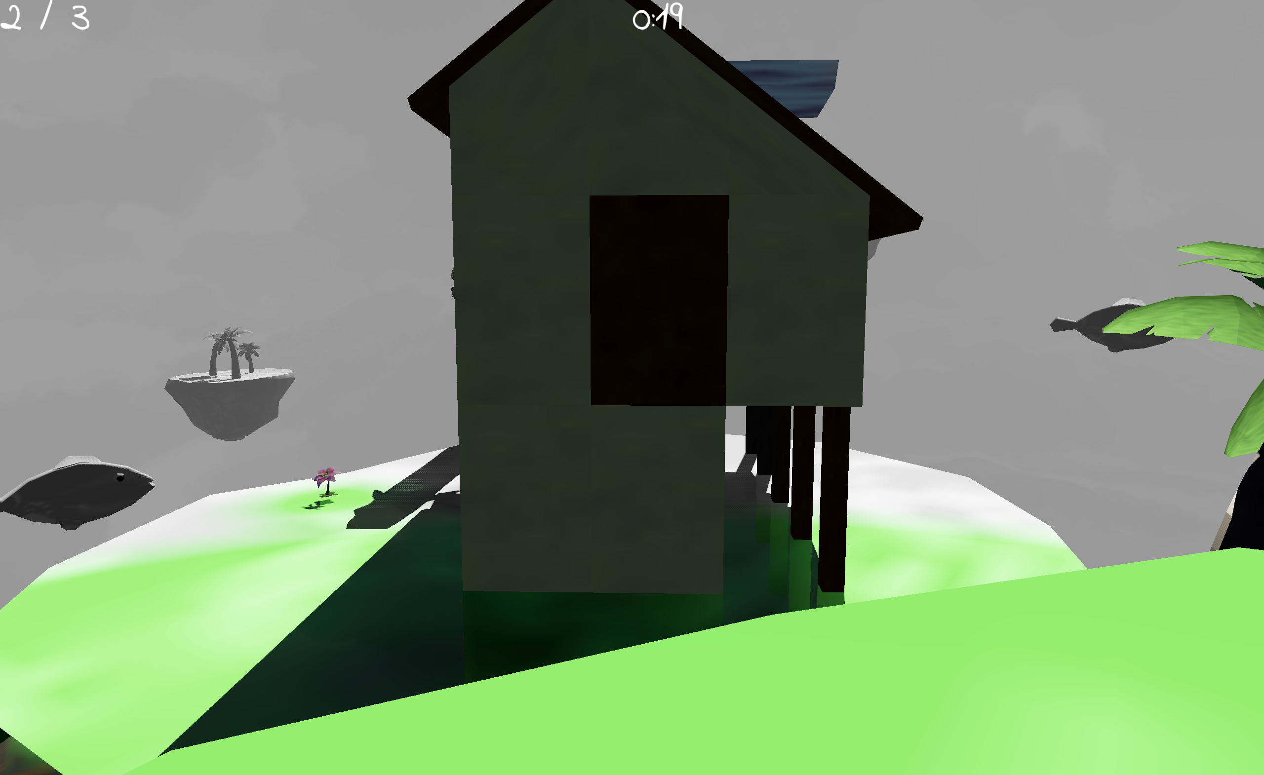
For coherency, we’ll examine a single frame in a level of SkyLei, with accompanying screen captures of each step as examined in Nvidia Nsight Graphics.
Depth pre-pass
All meshes are rendered. Only their depth information is outputted and stored on a depth map.

We opted to leave out support for transparent objects in the Lei engine, so there’s no need to alpha-blend in any other meshes later on. However, this depth map is still very relevant to a few steps further down the pipeline, so it’s useful to separate out this information early.
Shadow map generation
Shadow maps are regenerated every frame. All planned levels in SkyLei are outdoor scenes, so it was decided that we would only need one directional light. This saves some computation bandwidth and so we can also implement a version of cascaded shadows into the engine.
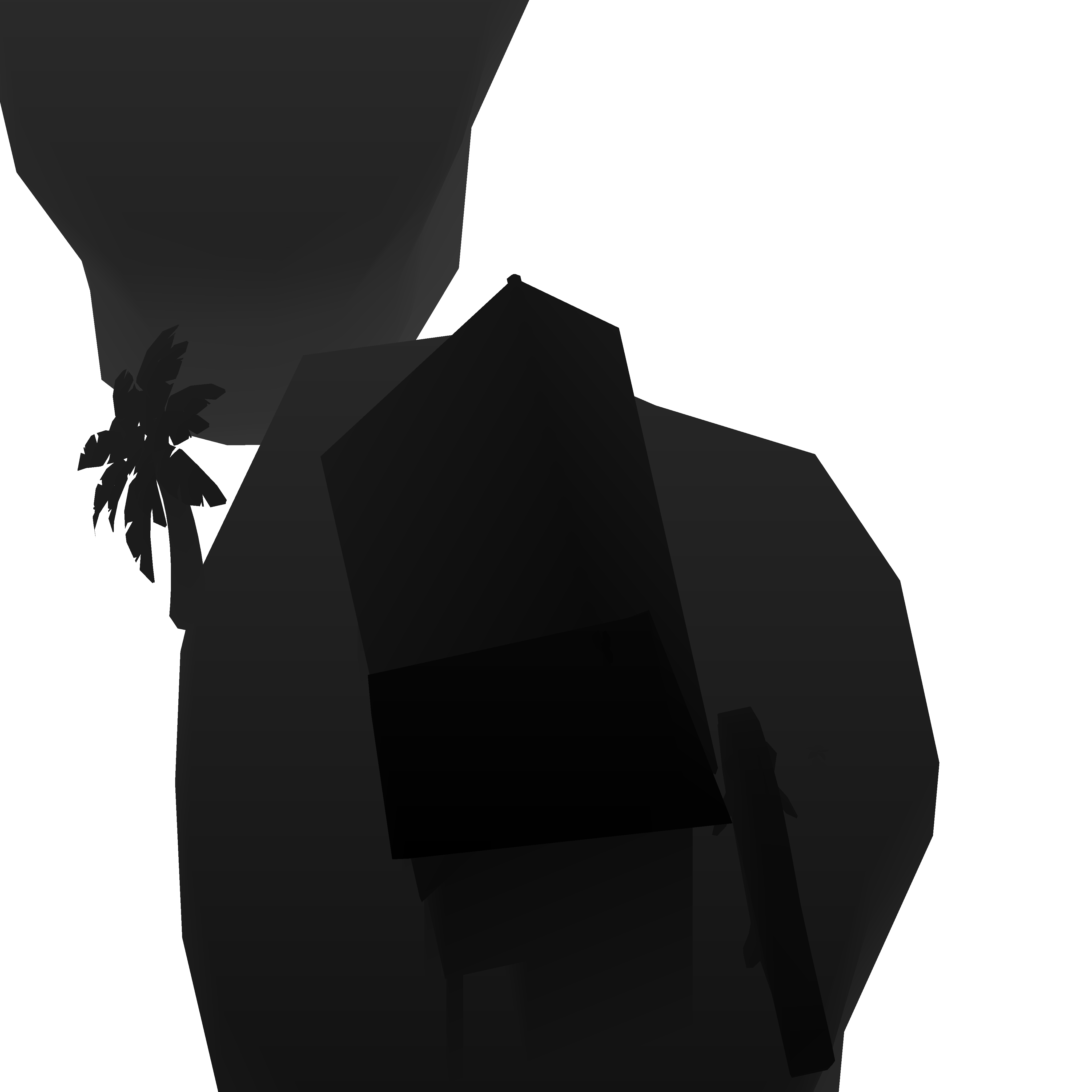
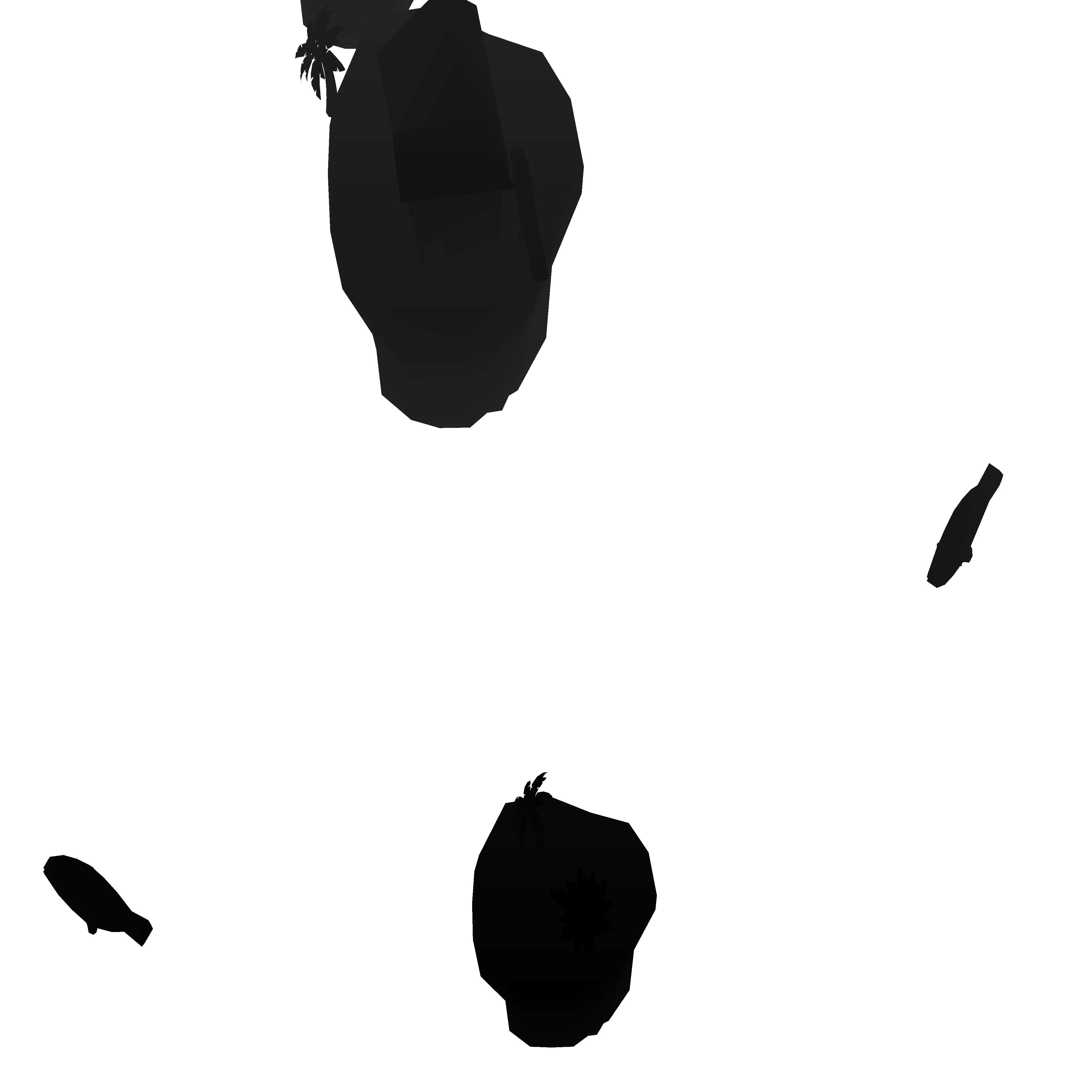


The shadow maps are simply just depth maps rendered from the perspective of the light source. Each cascade is stored in a level of the texture array and can be easily indexed later on when access is needed.
The idea behind cascaded shadow maps (CSM) is quite simple. Using a single depth map to generate shadows produces very poor quality results, especially for a sparse scene like SkyLei’s levels. So it’s better to use multiple textures to store this information. But how to do this efficiently?
We split the camera view frustum into different sections and assign each section a different texture. Then when we calculate the shadows for a rendered object, we can index for the appropriate texture depending on how far away the object is.
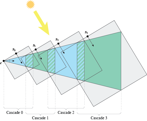
The result is that shadows closer to the camera (or the player) have more resolution, and shadows further away that are harder to see have lower resolution. You can see cascading in the slide above; in the 1st image, the player position is in the top left.
You may be interested in this Microsoft article that explains CSM and also offers a few different variations.
See: separating cascades using a geometry shader
Forward lighting pass
Now we render each mesh with lighting calculations. This is stored in a float HDR image buffer.
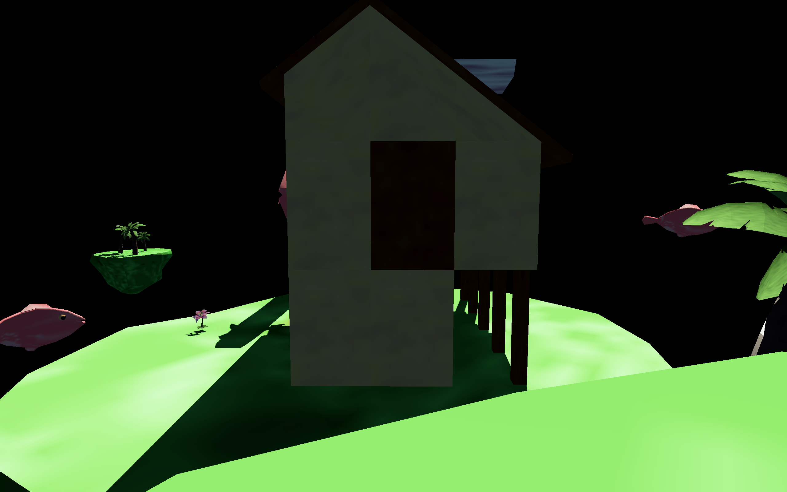
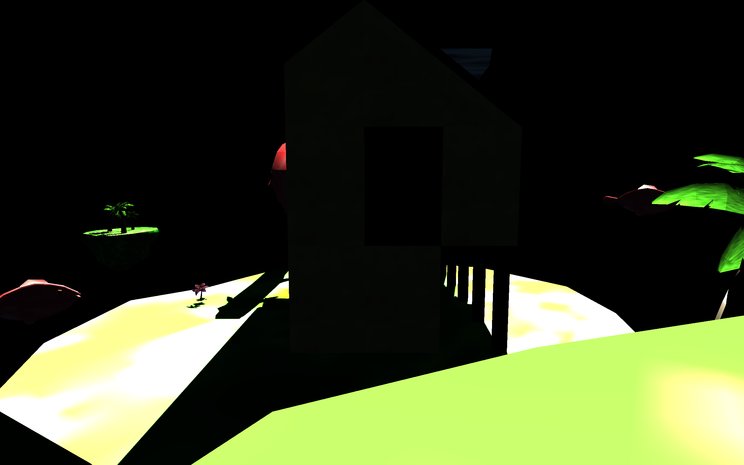
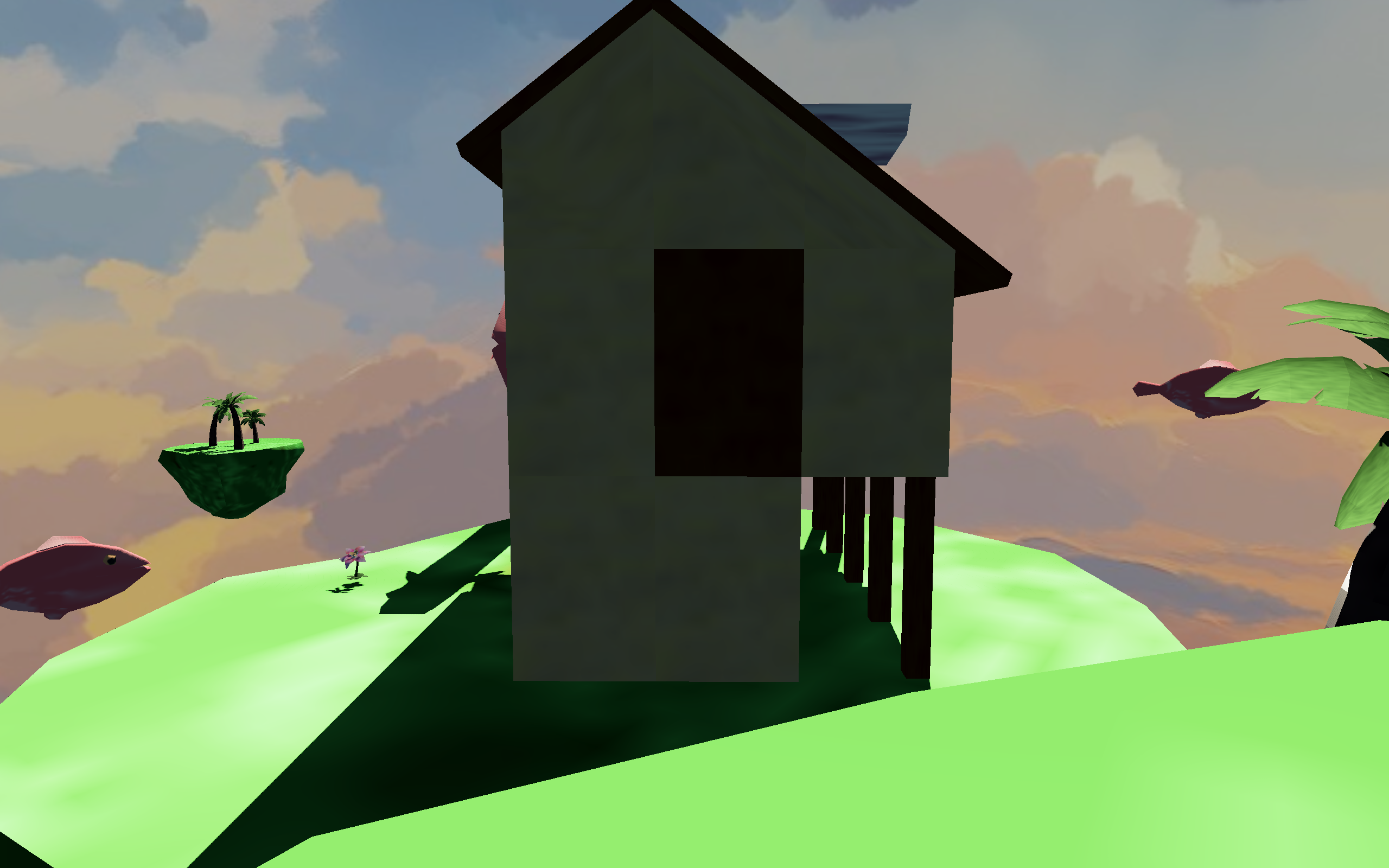
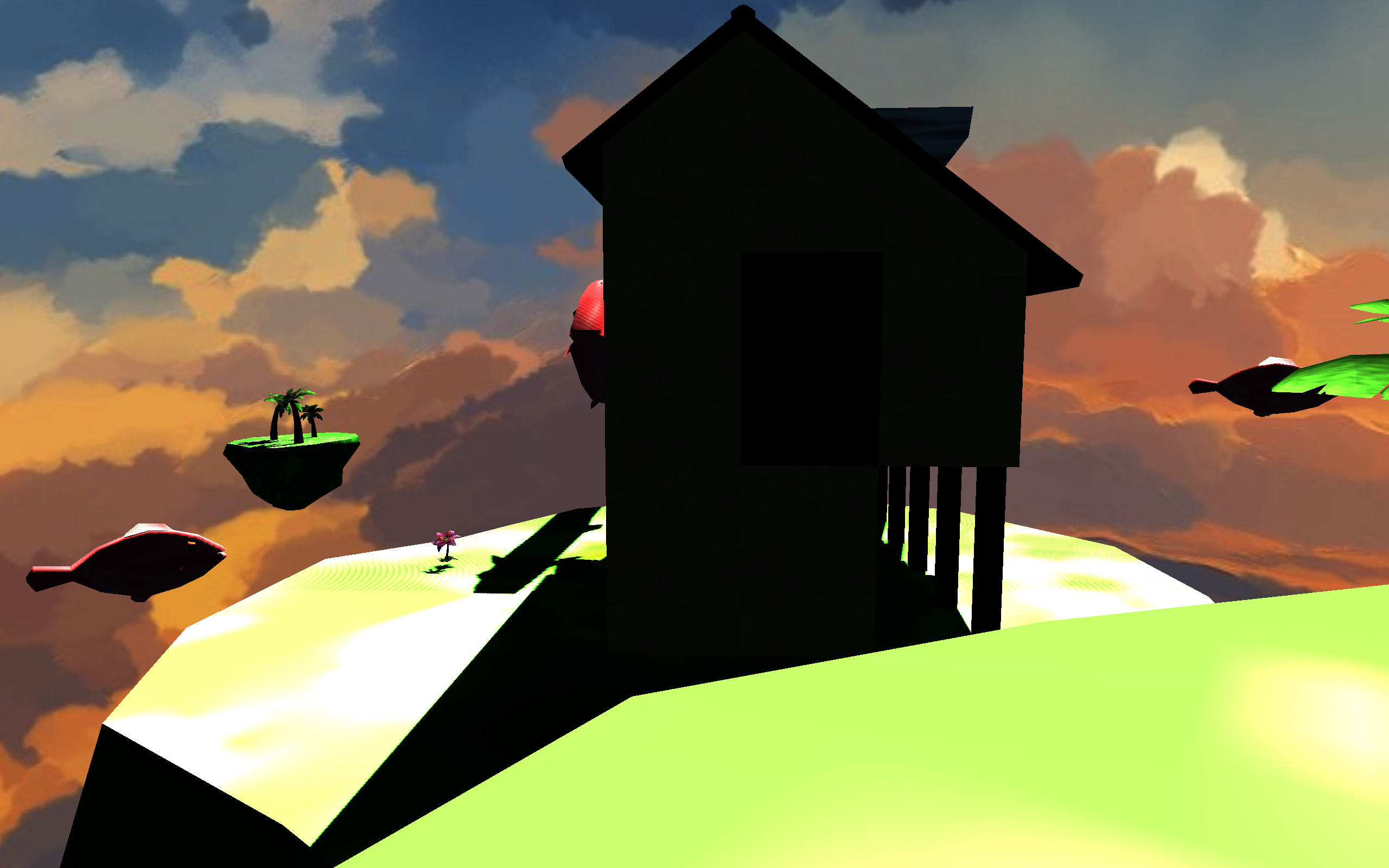
The 1st image in the slide has been tonemapped to standard dynamic range (SDR) to illustrate the colors and lighting. You can see the “raw” image buffer in the 2nd image. Many lighting values exceed 1.0 (or white) so are extremely blown out.
Other areas are dark because the buffer stores values in a linear color space and have not yet been corrected to sRGB for computer monitors (and your eye). This process, called gamma correction, happens later in the pipeline.
Lighting calculations in SkyLei use physically based rendering (PBR) materials. For the visual style of the game, the photoreal effect kind of works with the low poly meshes and textures. Although, I should also note that there is a flat ambient lighting factor added, so that all surfaces (even dark ones) are somewhat lit.
This step is also where the resources from the two former steps are used.
Depth testing is set to GL_EQUAL so redundant fragments are not rendered.
Using the depth map from the previous depth pre-pass, we know exactly which fragment each pixel has.
Shadowing effects are also calculated in this step, using the shadow maps generated earlier. Filtering (PCF) is applied to prevent aliased shadows and create a soft shadow effect. The Lei engine uses Poisson sampling with 32 samples, which I found to be performant enough for our uses and produce decent results.
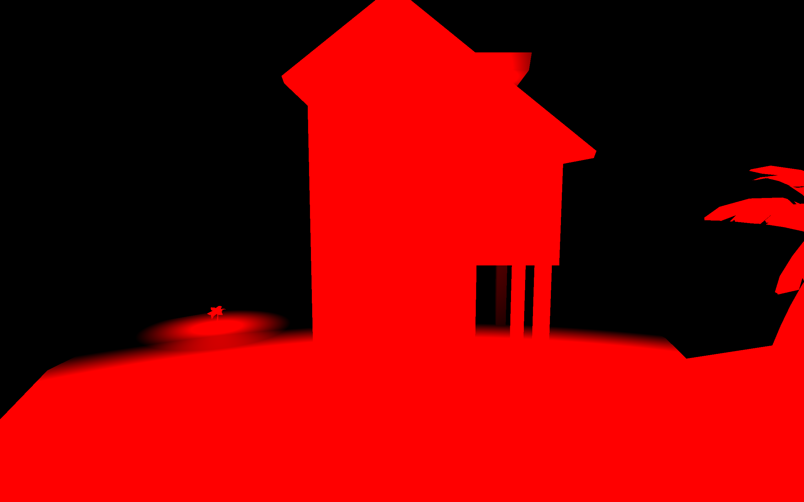
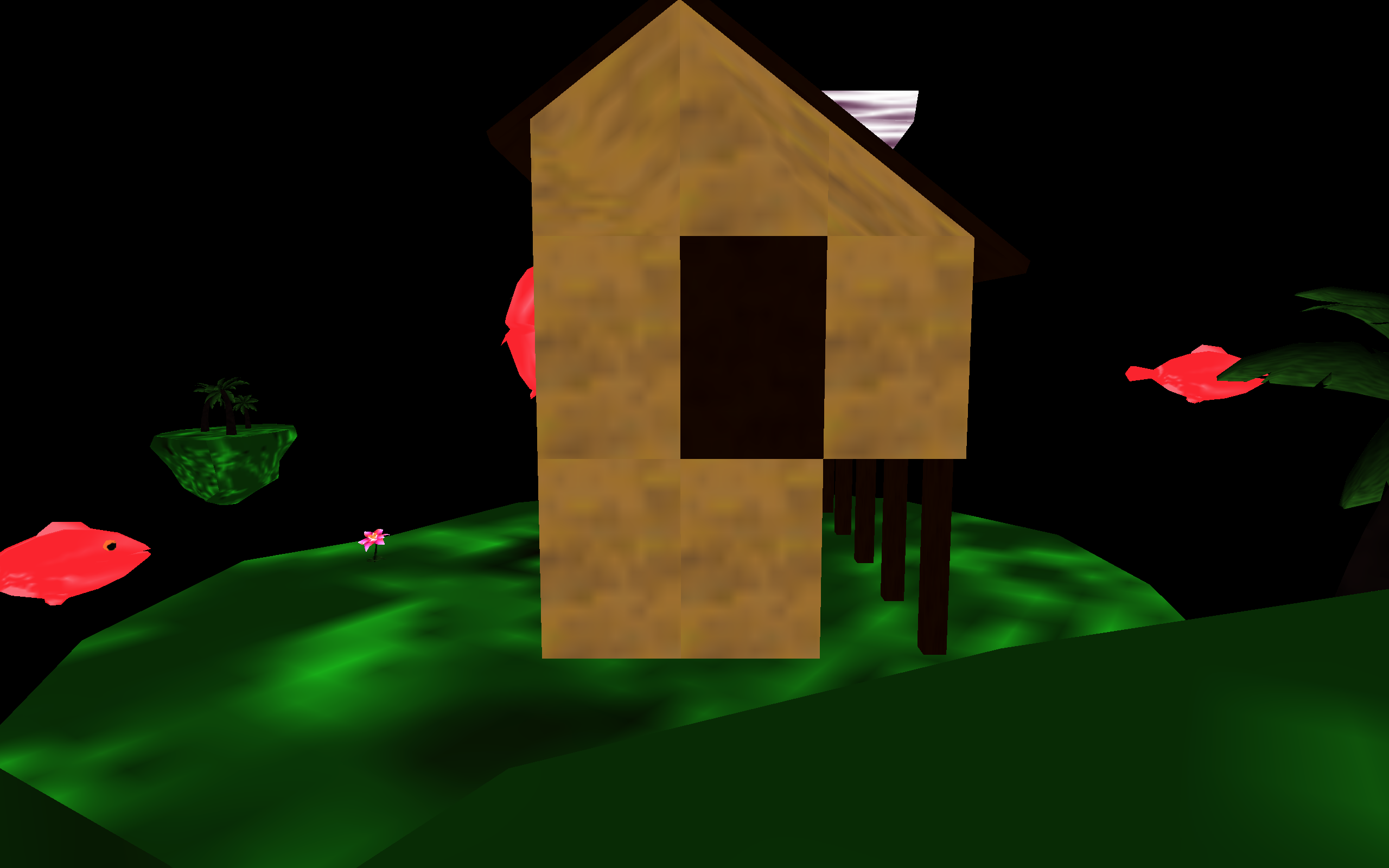
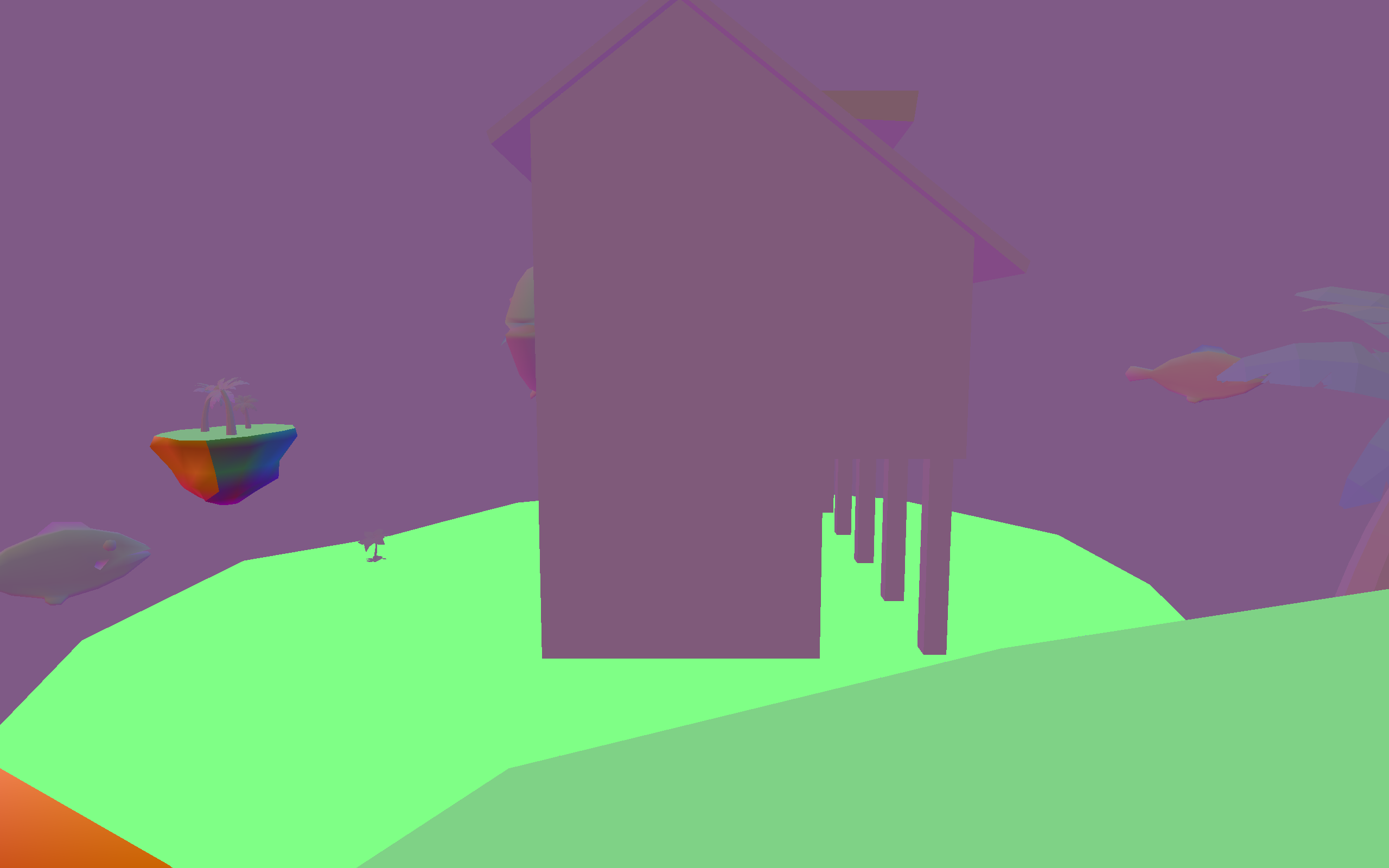
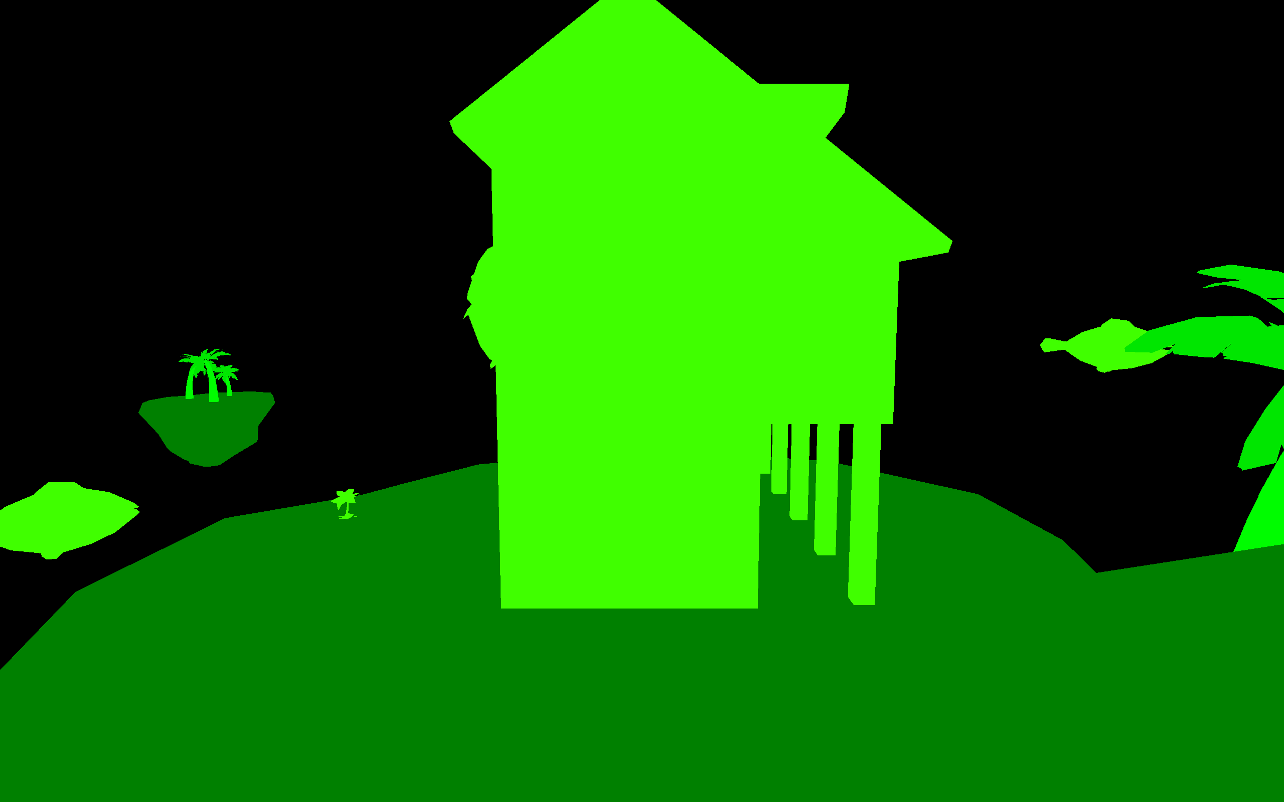
Additional information is also outputted to be used later on, as shown in the slides above. We do this using the multiple render targets (MRT) feature in OpenGL to write to multiple buffers in the same render pass.
The color saturation map is an engine feature made specifically for SkyLei; it’s not standard in a regular PBR pipeline. Since it’s only a single float value for each pixel, it is stored in a R32 float image texture.
The normal map is stored in the standard R32G32B32 float format in world space, though it is technically possible to only store two components and regenerate the third. The metallic and roughness values are stored on the same R32G32 float format texture, requiring only two floats per pixel.
See: forward pass shader
Environment cubemap
Now the environment map (the skybox) is drawn.
SkyLei uses the same sky texture across its different levels. It is laid out below as a cubemap.
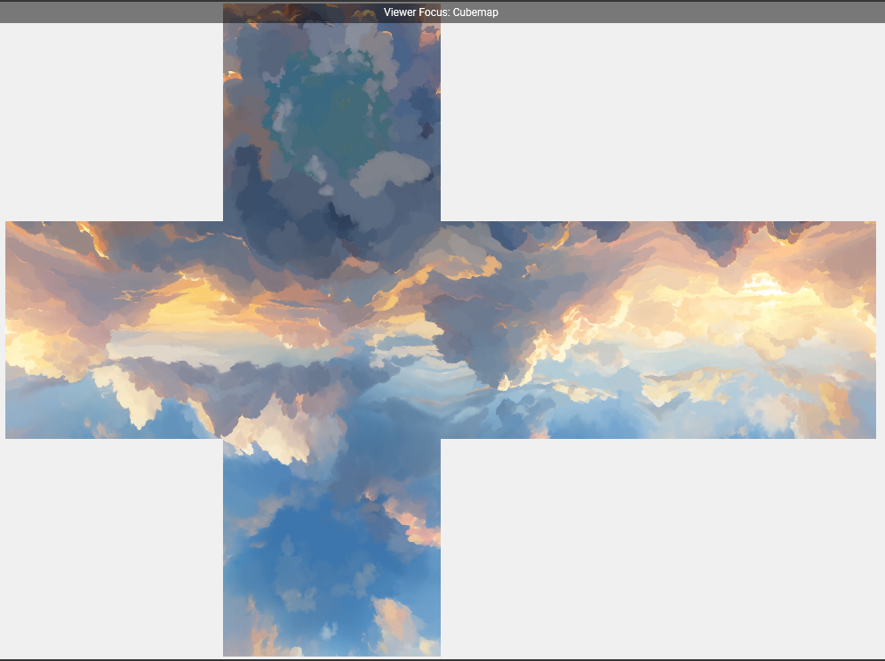
The color saturation effect in SkyLei also affects the sky, so in this step we also write to the same saturation buffer as the previous step. The calculation here is pretty simple. The distance from the color source “flowers” in the scene to the world boundary is calculated and the strength of its effects are weaker the further away it is. And due to the way cubemaps are rendered, the effect is still expands outward spherically, just as with the other scene objects.
See: skybox shader
Screen space reflections (SSR)
Next, the engine generates the SSR map, essentially a texture of reflections on objects in the scene. This effect is done by ray-tracing reflections using only information present on the screen, hence “screen space”.
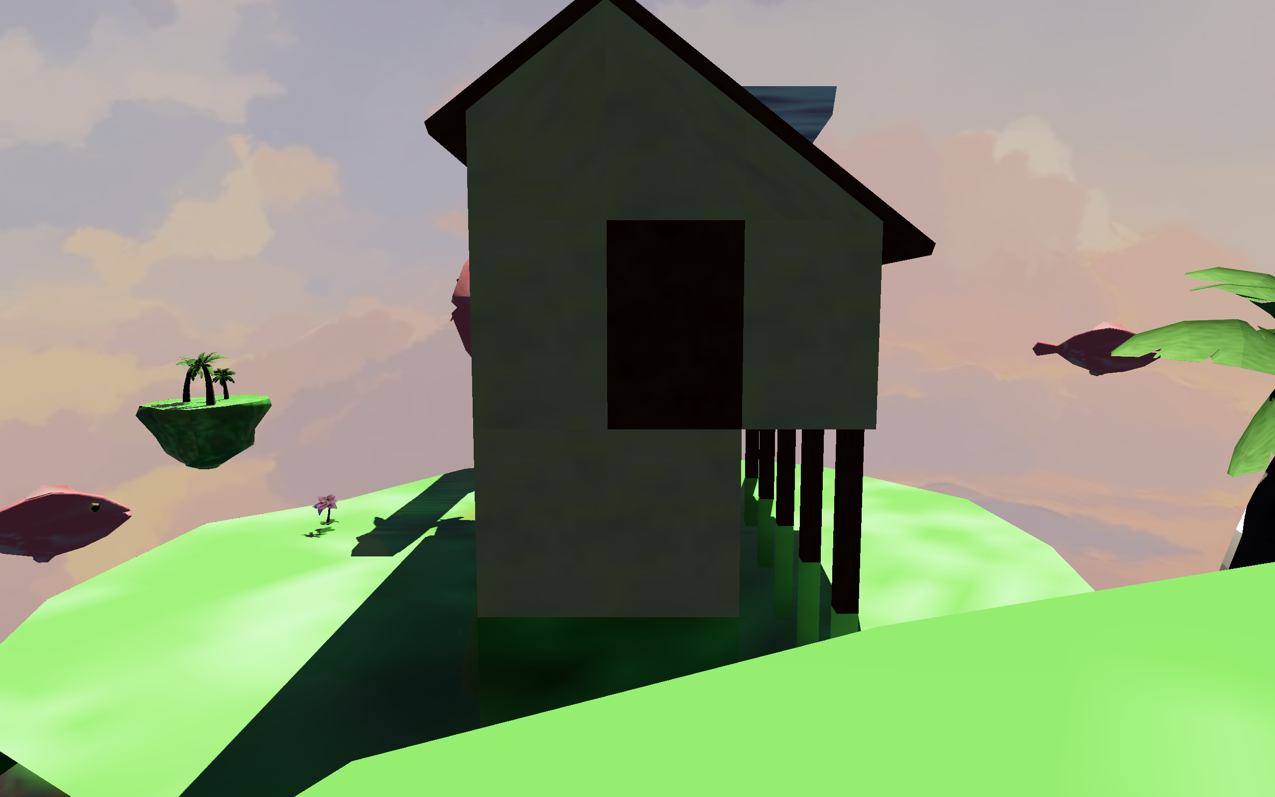
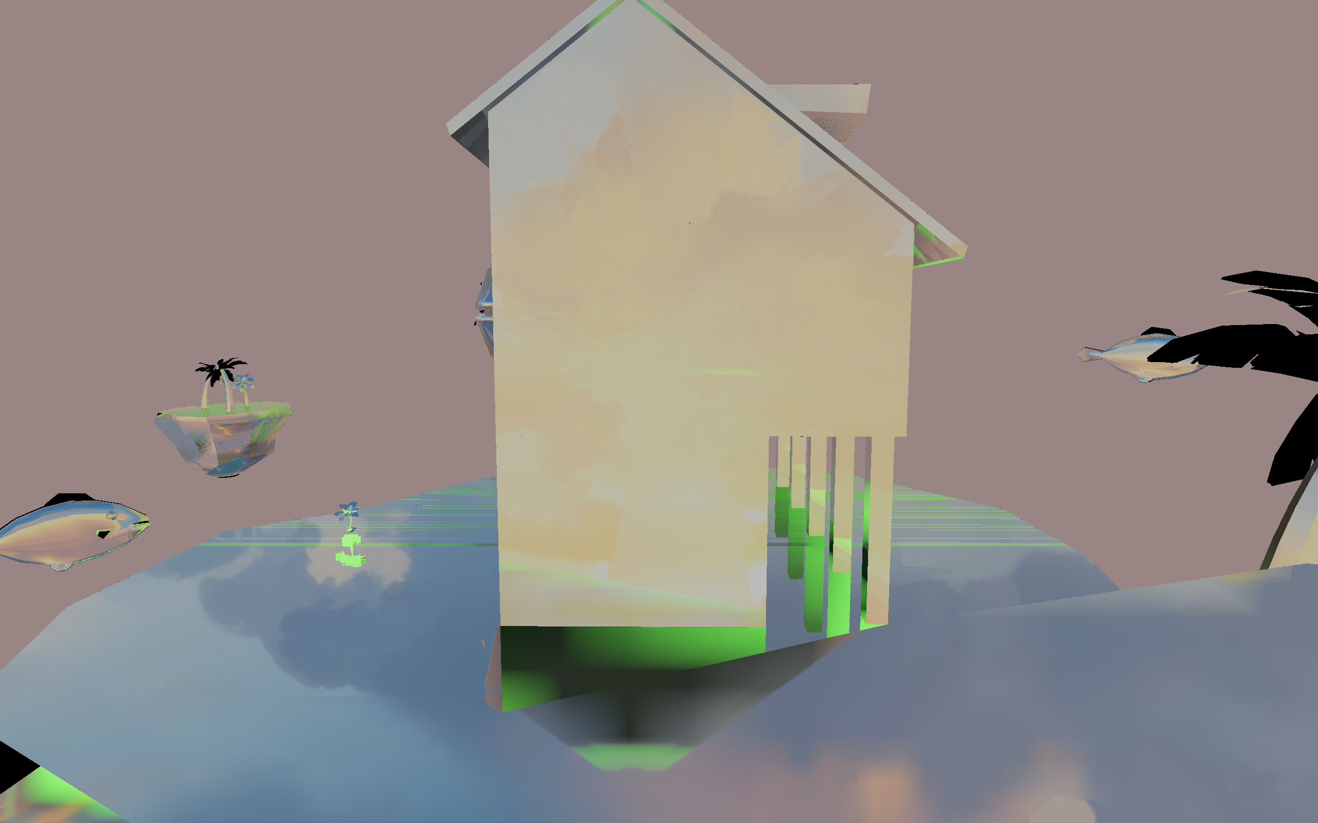
The SSR map is then blended additively with the lighting from the forward pass.
This step uses the information stored in buffers from all the previous steps, including the current lighting, albedo, normals, material roughness, and even the depth map used to calculate the world space position.
The ray-tracing algorithm for SSR is, in technical terms, ray-marching and is done in view space. There are a couple of variations for this algorithm but the Lei engine uses this one described by Morgan McGuire (who you should also follow if you’re interested in more graphics programming). Moreover, some more parameter tuning and additional effects can be done to make SSR perform better for SkyLei and reduce artifacts.
Below is an alternative view that showcases the reflections better. In this case, I also increased the reflectivity (metalness factor) of the material to illustrate SSR.
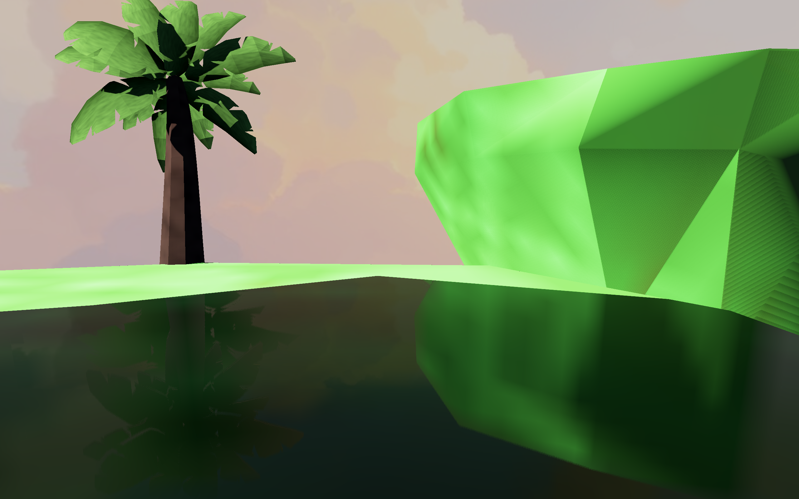
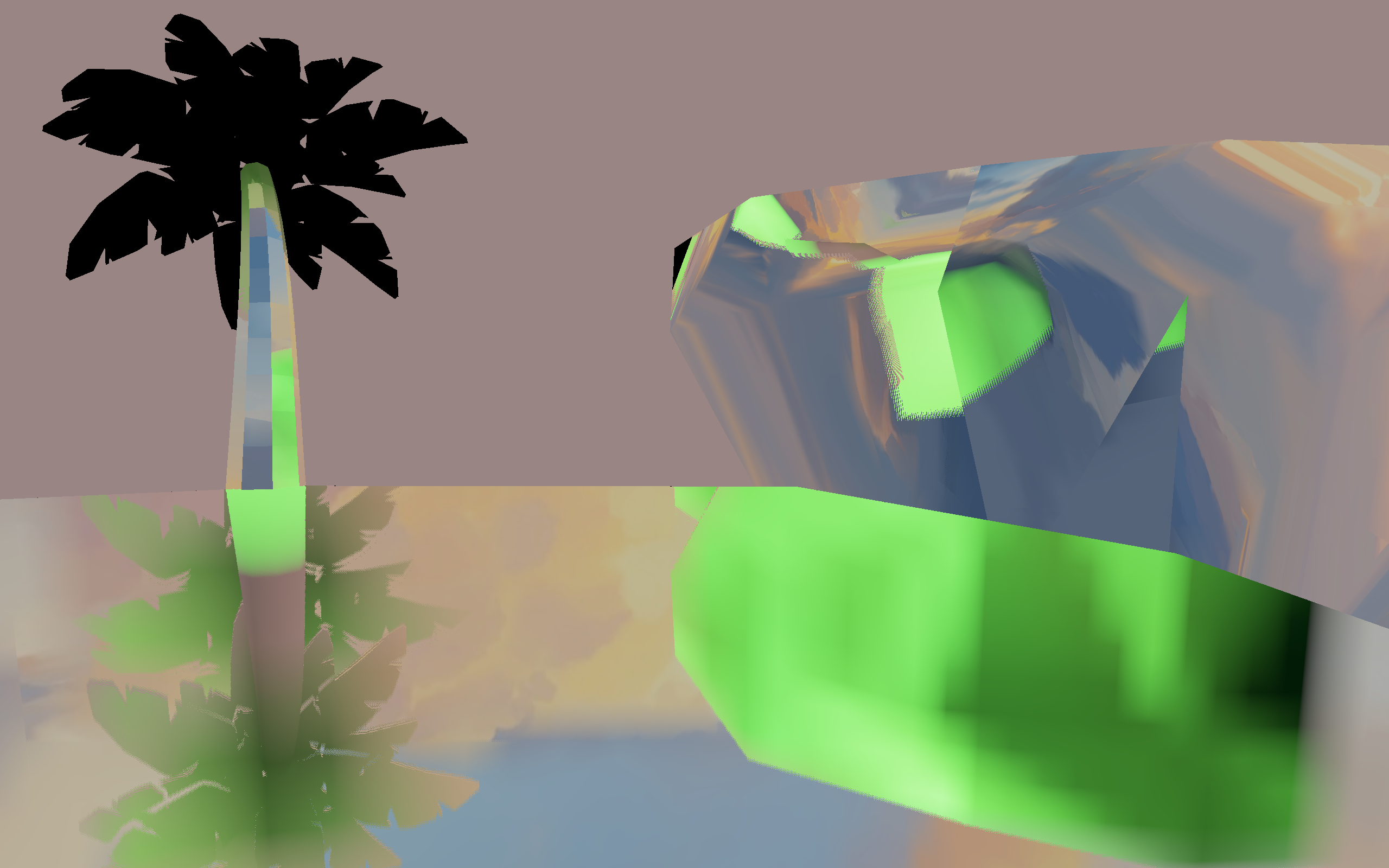
SSR is a nice, not-too-costly technique to produce reflections in real time. However, its limitations can be clearly seen above. Reflections of objects not rendered on screen do not exist, so as the player moves the camera downward, reflections begin to disappear. Also, to prevent clipping and visual artifacts of objects beyond screen borders, ray-tracing for SSR tends to terminate a certain distance from the screen border, and fallback to another method (usually and in this case, sampling from the environment map).
This blogpost was a great resource for me to understanding SSR in more depth and seeing the implementation explained step-by-step.
In other SSR implementations, instead of sampling the lighting from the current frame, the ray-tracing may sample from the previous frame of the game, where there is more complete information, such as particle effects or volumetric effects. Take this dev blog about Blightbound as an example.
See: generating SSR map and blending reflections
Post-processing
Finally comes the post-processing step. This consists of:
- blending in fog effect
- applying desaturation using the color saturation mask
- calculating average luminance of the whole screen and applying tonemapping

The fog effect is simple. The factor is proportional to the linear object distance from camera, as shown in the GLSL code below. Again, we make use of the information we rendered in earlier steps.
/*
 * color: current lighting value
 * depth: value from depth map
 * satFactor: factor from saturation map
 */
vec3 fogColor = vec3(0.24, 0.46, 0.675);
float fogFactor = depth * (1.0 - satFactor) - 0.2;
fogFactor = clamp(fogFactor, 0.0, 1.0);
color = mix(color, fogColor, fogFactor);
With tonemapping, we can take the high dynamic range (HDR) lighting buffer and convert to down to 8-bit per component SDR (0-255 as you may have heard). I borrowed the tonemapping algorithm from this Shadertoy example, which is a variant on Reinhard tonemap. Unlike flimic tonemaps, like ACES that’s used to emulate real film cameras, this one is less contrasty and fits more to the visuals of SkyLei.
If you’re interested in tonemapping and some different variations, this blog does a good job showing the algorithm and the differences in results.
UI
Even more finally, the UI elements are blended on top of the final frame. I didn’t have a hand in this part but an excellent job was done regardless, especially in handling UI layouts.

Potential improvements and closing thoughts
This is very much like a version 1.0 of the engine and the game, and there is much that can be done to improve it. For one, it would’ve been nice to decouple the rendering and the game logic onto different threads like this. It would also allow for faster asset loading, since the current loading times for each level is quite long.
But also there are many minor (and a few major) improvements that can be made easily to shader code for better performance. For example, I would advise anyone implementing SSR to not blur it the way I’ve done in the blending step; do a proper downsample and Gaussian blur!
What would’ve been really nice would be the ability to do baked lighting effects, like cubemaps for GI, which wasn’t added due to the limitations of time.
Nevertheless, this is a decent attempt at a version 1.0. Next time, needs a GL wrapper for sure.
Bonus reading and resources
- OpenGL reference pages for all your
manneeds - OGL dev as an alternative introduction to OpenGL
- PBR shading model by Unreal Engine used in SkyLei (and many modern engines)
I thought I’d have more to share here.
